Telecentric Lenses

Telecentric lenses are ideal for metrology because they do not exhibit perspective distortion. These lenses accept only light rays that are parallel with the optical axis. They are looking straight ahead across the entire field-of-view. Round holes look round, whether they are in the center of the image or near the edges.

Telecentric lenses improve the measurement of round objects or parts with rounded edges by visualizing the true outermost edges. A standard lens with perspective distortion cannot image the true outside edges of a round object due to its angle-of-view.

Telecentric lenses are also ideal for measuring features and surfaces that exhibit varying plane heights, since all objects within the specified depth-of-focus range of the lens will have the same magnification factor. This enables the vision system to provide improved metrology despite camera-distance variations to the features of interest.

Reduce Space Requirements with the CORE Series – These Lenses Provide the Same Field-of-View

Comparison of Standard and Telecentric Lenses

In the first set of images on the right, a standard lens is used. The object on the left has some thickness and a large hole runs though the center of the part. The bottom of the hole has a smaller measurable diameter than the top of the hole and you can see the side walls of the hole because of perspective error or the “angle-of-view” emanating from a standard lens.

In the image on the right, the bolts are at different distances to the camera. Although these bolts are the same height and diameter, the closer bolt looks and will measure larger in both diameter and height than the bolt that is farther away from the camera.

In the second set of images, a telecentric lens is used. Note that there is no perspective error; the view is straight through the part with the top and bottom of the hole being the same diameter, and with no visible side wall inside the hole.

In the image of the bolts, although the bolts are physically staggered, both will have the same measured diameter and height because both are within the depth-of-focus of the telecentric lens. Any metrology done on the bolts will yield the same results.

To discuss whether a telecentric lens will help provide the results required, please contact R.J. Wilson, Inc.

Images Provided Courtesy of Opto Engineering®

Images Provided Courtesy of Opto Engineering®

OPTO ENGINEERING’S Bi-TELECENTRIC CORE SERIES LENSES REDUCE IMAGING SYSTEM LENGTH UP TO 70%

Opto Engineering’s bi-telecentric lenses have been the performance standard for decades. One of the challenges with standard telecentric imaging and lighting components is dealing with their length and working distance requirements in terms of the available mechanical height.

The CORE Series of bi-telecentric lenses feature an ultra-compact opto-mechanical design that reduces the overall size and working distance of a telecentric configuration by up to 70%. By significantly downsizing the imaging system, telecentric components can be used in more space-limited applications for precision metrology.

The unique shape of the CORE lenses has been developed for maximum mounting flexibility. They can be mounted in different directions using any of the 4 sides, without clamps, to fit or retrofit the lenses and lights into more compact machines.

The TC1MHR to TC4MHR CORE lenses can support image sensors from ½” to 4/3”, with C-mount, F-mount, and M42 mounts available. The available magnification range within this series is 0.052X – 0.369X, depending on the lens and sensor combination.

TC3MHR-5MHR CORE+ lenses are large field-of-view telecentric lenses that support image sensors up to 4/3”, with C-mount and F-mount options. The available magnification range is 0.053X – 0.117X, depending on the lens and sensor combination. With a 4/3” image sensor, objects as large as 260mm may be inspected while maintaining telecentricity.

The CORE+ lenses are specifically designed to accurately measure large objects in a reduced space. Their folded optical path permits large FOV imaging, while keeping the overall footprint compact. The size reduction is up to 45% compared with standard telecentric lenses and lights for large fields-of-view.

VST VS-LTC Series Large Format Telecentric Lenses

The use of ever-larger camera sensors comes down to throughput – if we can increase the size of the field-of-view and maintain the measurement accuracy required, we can be more productive in the same amount of cycle time. Whether an automated vision system is inspecting LCD panels, wafer die, solar panels, or other critical features, this is a benefit.

VST’s VS-LTC Series telecentric lenses keep up with the increase in sensor size, supporting an image circle of 45mm while providing 1X, 1.5X, and 2X magnification lenses at a working distance of 130mm. Each lens is available with a diffuse coaxial illumination system. The VS-LTC lenses support current major large-format image sensors, including:

  • 25MP:5µm/pix(φ32.5mm) 
  • 29MP:5µm/pix(φ43.8mm)
  • 71MP:1µm/pix(φ38mm)

The VS-LTC lenses include F-mounts, with adapters available for M42, TFL, and M58 cameras.

Telecentric Backlighting Supports Proper Metrology on Cylindrical or Rounded-Edge Parts

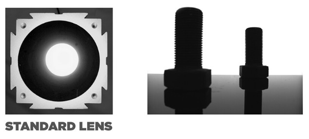
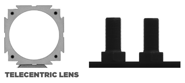
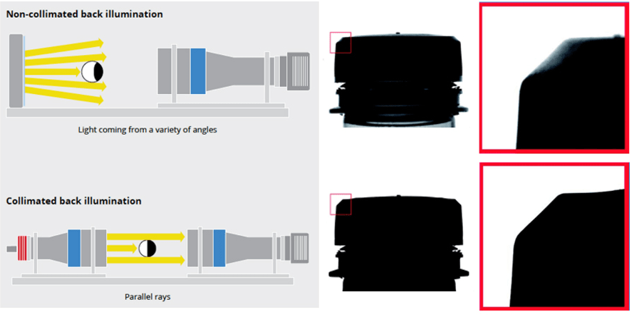
Telecentric lenses are ideal for imaging parts that are cylindrical or have rounded edges because they do not suffer from perspective distortion and are truly imaging the outermost edges of the part. But what about the lighting?

It may be surprising that when using a standard backlight or a backlight using collimation film, it’s possible for the light to “creep” around rounded edges and create “false edges” that might be incorrectly detected by the vision software.


This happens because standard backlights emit light at all kinds of random angles. Backlights using collimating film are only “collimating” to +/- 30°. This is generally acceptable for imaging parts with straight, flat edges, but even collimation film may not be adequate to fully eliminate the appearance of false edges on rounded parts.

By using a true telecentric backlight, the light rays are nearly perfectly parallel as they emanate from the backlight. A typical fully-telecentric imaging configuration includes a telecentric lens and a telecentric backlight to ensure the light is creating and the lens is accepting only parallel light rays, achieving a truly “silhouette” image with no perspective error. The parallel light rays are not going to create the false edges, illustrated above, that may affect where the edges are located by the vision software and, thus, compromise measurement accuracy.

Opto Engineering’s newest CORE and CORE+ Series of lighting provides true telecentric backlighting in a much more compact package, for situations with limited space or to retrofit an existing imaging system.

Please contact R.J. Wilson, Inc. to discuss your telecentric lens and lighting requirements at 781-335-5500 or [email protected].