RJ Wilson | Imaging Components for Industry & Science
Menu
Standard Lighting
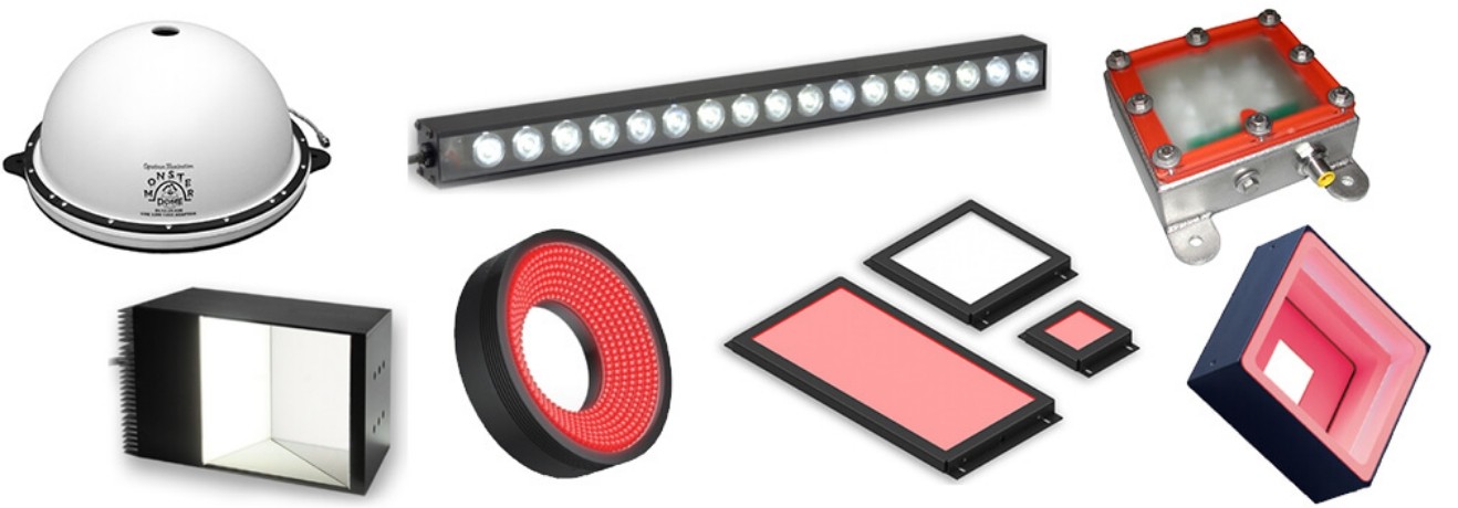
Standard LED lights are offered in a wide range of shapes, sizes, working distances, coverage areas, wavelengths, and lighting techniques. There is generally an “ideal” lighting configuration for your specific application.
With literally thousands of choices, R.J. Wilson, Inc. and its lighting partners have the real-world experience and technical know-how to help you select a lighting configuration that is optimized for your application requirements. Let’s discuss the options available. Lighting is the most important aspect of a machine vision imaging system, so it’s worth the upfront work to evaluate the lighting to be sure it’s a proper match for the application.
Things to Consider
FORM FACTOR
The goal is to select a lighting technique, position, and shape that properly illuminate the object to make the features-of-interest, edges, or regions reliably and repeatably visible to the inspection software.
Spectrum Dome, AI Backlights, AI Bar, AI On-Axis, CCS FPQ, CCS Ring, SVL Brick
There are thousands of variations of the lights available from our brands. The CCS document below provides an overview of the available lighting form factors and how different light-delivery formats may affect the appearance of objects. This document is a summary and should be followed up with an application discussion.
In selecting a form factor, we think about how the light is going to reflect off the object and the background, and back to the camera. We don’t want to create additional specular highlights, reflections, and other image artifacts that may affect the quality and consistency of the acquired image by adding confusing features.
WAVELENGTH
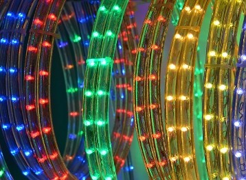
Available LED wavelengths range from the ultraviolet, through the visible colors of the rainbow, and into the infrared. The selection of a lighting wavelength depends on numerous application factors. The goal is to make the features-of-interest more visible for the vision software to detect and distinguish from the surrounding area.
When visible light imaging is used, the LED color/wavelength can be used to enhance the features-of-interest or defects, making them more visible to the vision system. These lighting enhancements are based on how various materials, object colors, textures, and other traits reflect or absorb light at specific wavelengths.
Download the CCS Wavelength Guide below for an overview of the effects of UV, visible, and NIR LED wavelengths on the appearance of objects in the acquired image.
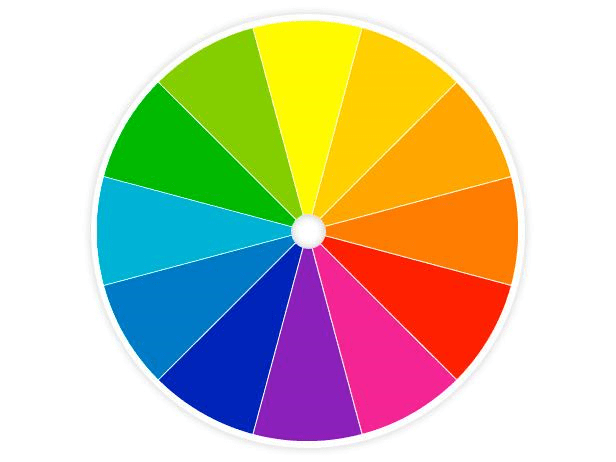
When using a monochrome camera, the selection of the LED wavelength can determine whether a specific color feature in the object is enhanced or diminished. The use of an LED color close to the object color will lighten its appearance in a greyscale image. The use of a light color on the opposite side of the color wheel from the object color will darken it.
More examples of using color to enhance or diminish the appearance of a specific color in a visible light monochrome image may be found on our Filters page. The bandpass filter effects shown are similar to those of various LED light wavelengths when imaging in monochrome. This is why a white light may be used with a bandpass filter on the lens to pass only a specific color.
· Keep in mind the spectral response curve of the camera’s imager when selecting a lighting wavelength.
Ultra-violet (UV) imaging
For information on lighting with UV (Ultra-Violet) LEDs to take advantage of fluorescence imaging, please visit our UV Lighting & Imaging page.
Visible light is not always ideal for some challenging applications. Near-infrared light, typically at 730nm, 850nm, and 940nm, is more effective at penetrating certain materials than visible wavelengths. Near-infrared light’s longer wavelength often allows for less scattering from part surfaces and higher transmission rates through them. Higher transmission means the NIR light can pass through more materials, making it ideal for inspecting for part presence within packaging, detecting fill levels, or imaging foreign matter.
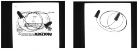
IR Light is Used to View Through the Printed Package to See the Ear Plugs Inside
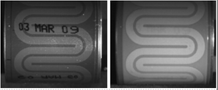
In the image below, white light is used on the left and near-infrared light is used on the right. The NIR light is not reflected from the printed date code, permitting the vision system to see and inspect only the object underneath.
White Light Shows the Date Code, Near-Infrared Lighting Passes Through the Printed Code
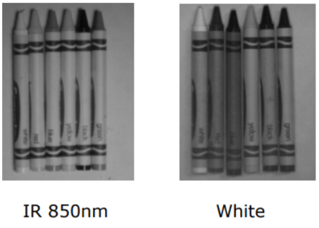
Near-Infrared (NIR) Lighting – Diminishing Color
NIR light is effective at neutralizing or reducing contrast differences based on color in monochrome images, primarily because the reflection of NIR light is based more on sample composition rather than color differences. This property can be used when less contrast or the reduction of the effects of color is desired.
Near Infrared Light Can be Used to Diminish the Greyscale Differences Between Color Objects
SHORT-WAVE INFRARED (SWIR) IMAGING
Selecting the most appropriate lighting for an application is partially based on how an object and its background absorb or reflect light at the wavelength in question. SWIR wavelengths are typically 900nm to 2500nm. For some applications, the use of Short-Wave Infrared (SWIR) Imaging may be required:
· Differentiating clear adhesives from the background.
· Detecting the liquid fill level in an opaque bottle.
· Differentiating between clear liquids.
· Viewing through silicon to inspect the alignment of bonded wafers.
· Detecting cracks in a solar cell.
· Seeing through opaque plastic packaging to verify the contents.
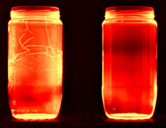
· Inspecting just-formed hot glass for stress cracks that could result in a bottle or jar failure in processing or at the consumer level.
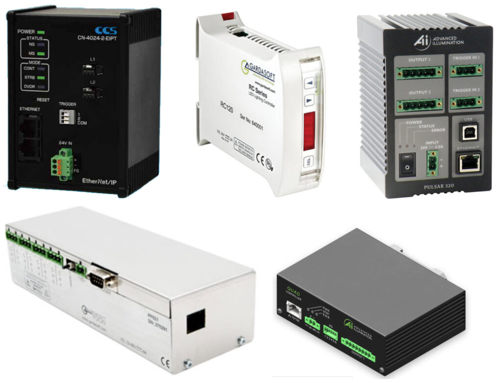
Internal and external light controllers are available to help tailor the lighting configuration to the image acquisition methods and application requirements. Please visit our Controllers page for more detailed information.