Computational Imaging

Computational Imaging (CI) in Machine Vision is basically the ability to use multiple separately-acquired images, each created with a particular lighting or imaging technique, to create a single resulting “optimized” image that is based on processing the individual images to end up with a single computed composite image.

The key principles of Computational Imaging are:

  • Computation is inherent in the image formation process
  • Combines special optics and/or lighting, along with image processing, during the image capture process
  • Typically involves capturing a sequence of images using a different illumination technique, wavelength, or optics for each frame
  • Covers a wide variety of techniques, all designed to output more useful composite images or composite images with unique characteristics

WHAT TYPES OF APPLICATIONS CAN BE ADDRESSED WITH COMPUTATIONAL IMAGING?

PHOTOMETRIC STEREO (PMS)

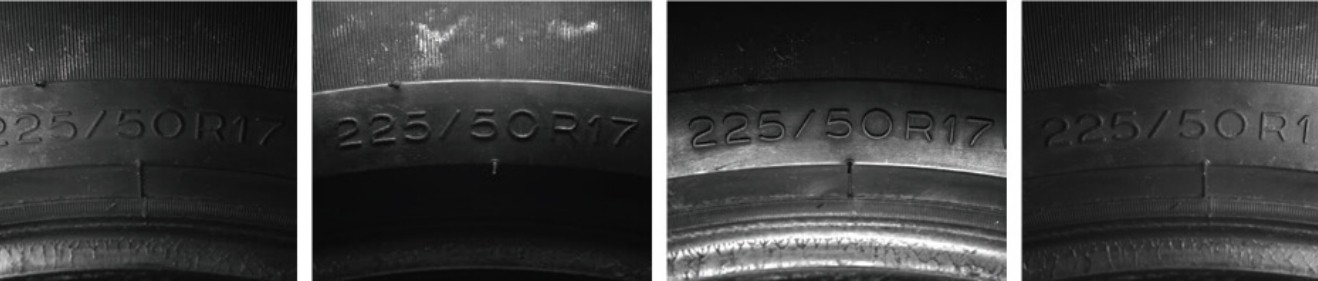
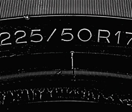
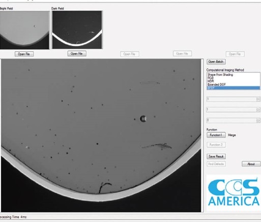
Generate edge and texture images using shapes resulting from light shading. Photometric stereo allows the user to separate the shape of an object from its 2D texture. It works by sequentially firing segmented light arrays from multiple angles and processing the resulting shadows utilizing “shape from shading.”


This can make visually noisy or highly reflective surfaces easier to inspect by removing these artifacts from the computed image. Numerous machine vision companies are now offering photometric stereo tools that control sequential image acquisition and image processing within their vision software and smart cameras.


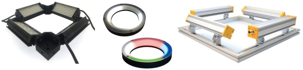
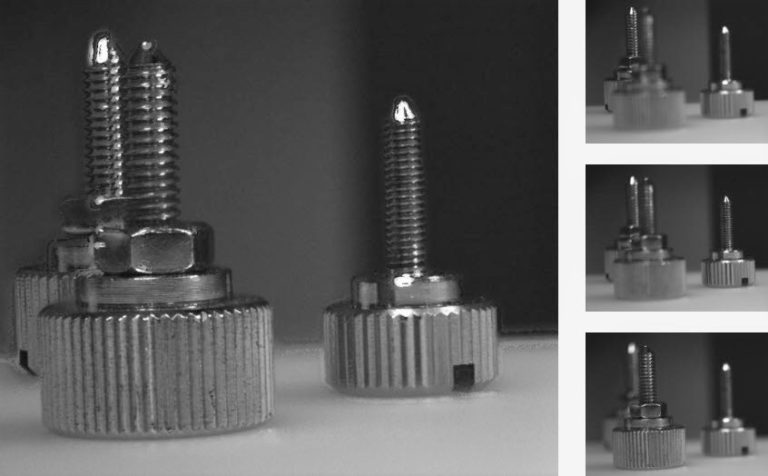
As an example, a basic PMS system may utilize a ring light with four individually controllable 90-degree quadrants to cast a directional shadow around the raised features on an object. The ring light quadrants were fired in sequence to create directional images shown below:

The image of the tire sidewall’s character shapes is created by combining these four images in software, as shown to the right. The presentation of the characters is now suitable for use with OCR or OCV.

Can Computational Imaging Be Used on a Moving Object?

Photometric Stereo can be used on a moving object if 1) the entire region-of-interest remains in the field-of-view throughout the capture of the sequential images required AND 2) a common reference pattern appears in each sequentially-acquired image so that the acquired images may be aligned to the common reference pattern in software during processing AND 3) the vision software used supports this function.

 For example, when processing a photometric stereo image, there are 4 quadrant images and a 5th pattern-training image to be acquired and processed. The alignment pattern must appear in all 5 images and is used to align the 4 individual lighting quadrant images for processing, despite the alignment pattern’s slight movement and different position within each image. 

Given the high-speed acquisition rates of today’s cameras and the nearly instantaneous pulsing of the light sequence, the benefits of CI can typically be applied to moving objects, depending on their speed and size.

WHAT TYPES OF LIGHTING ARE USED FOR PHOTOMETRIC STEREO?

When performing Photometric Stereo imaging, the light is provided in a sequence that includes a West, North, East, & South image. As seen above in the tire example, the light is shown coming from the 4 sides. By combining the individual images, the computed image of the raised tire numbering  is created. 

The selection of the appropriate lighting for Photometric Stereo is based on the sample size and shape. A typical light is a segmented ring light. Each “quadrant” of the light flashes in sequence, creating the directional lighting. The software used controls the acquisition process to gather the individual images and provides the computed composite image.  

Small Square Bar Light, Segmented White & RGB Ring Lights, Large Square Bar Light Configurations

 As the samples get larger in size, 4 larger bar lights, arranged in a square configuration, may be used. The lighting configuration can be as large as is needed, provided there is sufficient light coming from each direction to create the CI images.  

ULTRA-RESOLUTION COLOR (URC)

Create higher-resolution color images with no interpolation artifacts. By using a higher-resolution monochrome camera and acquiring separate full-resolution monochrome images using red, green, blue lighting, a full-resolution composite image with improved color fidelity and minimal color noise is computed. Because there is no color filter used in the camera or color interpolation artifacts within the computed image, the image is enhanced for manual interpretation and archiving (medical testing). Plus, this technique will provide a higher-resolution per color channel than a 3-chip color camera.

The technique of multiple image acquisitions also applies to using any combination of LED wavelengths to visualize features-of-interest, including UV and IR lighting.

Graphic Courtesy of CCS America

BRIGHT FIELD/DARK FIELD

Combine the advantages of two well-known lighting techniques.
Bright field and dark field are two common methods of illumination for machine vision inspection. Normally, they are used independently, as most samples image best using one method or the other. But what if your sample contains some features that can only be seen with bright field, and other features that can only be seen with dark field?

Multi-shot imaging solves this problem through the use of a combined bright field/dark field illumination technique. The bright field image is combined with the dark field image to generate an output image which contains the features or defects found in both input images.

Graphic Courtesy of CCS America

Shape and Texture from a Single Image

Generate both a Shape Image and a Texture Image using Photometric Stereo techniques. In this example, characters are embossed into the packaging directly on top of a linear barcode. While the barcode is for point-of-sale use, the embossed characters contain important lot code and expiration information. The embossed characters are difficult to see by eye, but they are readable by a vision system using Computational Imaging techniques to create both a Texture image (the barcode) and a Shape image (the embossed characters). 

Computational Imaging Provides a Texture Image (left) and a Shape Image (right)   

The use of Computational Imaging permits the viewing of each type of information. A segmented light source was used to create the image and the computed image is manipulated to highlight the appropriate information in each view.   

Extended Depth-of-Field

All images have a depth-of-field (DOF), a distance over which objects appear in sharp focus. In any single image, DOF is limited by the magnification and aperture size used. In some machine vision applications, the DOF may not be great enough to focus sharply on all the objects in a scene. Conventional solutions for increasing DOF, such as closing the aperture (higher f/#), come with substantial tradeoffs, such as decreased light intensity and reduced resolution. 

The EDOF (Extended Depth-of-Field) Computational Imaging technique allows an image to be created with a DOF greater than any of the single images. Using EDOF image processing software and the appropriate illumination, multiple images with various depths-of-field can be merged to return a clear, sharp result – without loss of light or image resolution. A separate liquid lens & controller or additional lens or motion control techniques are required to create EDOF images. 

What Types of Lighting Controllers are Used for Computational Imaging?

There are 2-channel, 4-channel, 8-channel, and 12-channel lighting controllers available to provide the means to synchronize image captures between the camera and one or more lights, depending on the CI technique used. The lighting controllers are standing by waiting for a trigger signal to initiate and coordinate the camera’s image capture with the programmed lighting sequence.  

Communication and triggering of the lighting controllers by the selected machine vision software are done via an Ethernet connection or discrete IO.

Computational Lighting Controllers from CCS, Gardasoft, and Advanced Illumination

The acquired CI images are processed in software to create the computed image. The CCS LSS-2404 Computational Imaging Light Controller includes software from Silicon Software that is used to control acquisition and creates the computed image that is then transmitted to the vision system software for analysis.  

 Many vision system OEMs now include Computational Imaging software within their libraries, including Cognex, Halcon, Matrox, Teledyne Dalsa, Omron, and more. (R.J. Wilson, Inc. does not sell software or hardware products from these companies). 

There are hundreds of lighting and control options available for bright field/dark field, high-resolution color, multiple lighting wavelengths, or “shape from shading”. R.J. Wilson, Inc. is ready for a conversation to help determine the most appropriate technique and lights to use, based on the application requirements.